Cherry Hau

Detailed houses in Winchester, modelled to represent a point in history as assets for game engine.
In this project, I worked to create representations of buildings in Winchester as they would have looked around the year 1800, with the end goal being to have the whole of Winchester recreated and explorable in the Unreal game engine. I modelled number 15 (and 15A), and number 16 on Kingsgate Street.


The aim of Virtual Cities Winchester is to have the whole city of Winchester represented in different time periods and be able to showcase stories of artifacts and different ways of life around a virtual 3D environment; this would be used to create an interactive experience which would increase interest in archaeology and history.
Our focus for this project was on the Jane Austen period, which is around 1800. As a 3D Visualiser, my task was to prepare 3D assets for use in the Unreal project.
The building of my focus was 15 Kingsgate Street. Due to its proximity to the cathedral, it would be required to be included in the project scene. This building offers a lot more potential than initially visible and could showcase a different way of living very well through its unusual architecture.
Whilst there does not seem to be any records of any person of interest having lived there, the building has a diverse history and is culturally interesting even in its construction. It has changed hands many times, from most recently being converted and split into multiple private residences, it has been owned by the Winchester College for housing sick students, to previously being a large private house and stable.
One of the distinctive features of the house is that it is split into three distinct sections, each built on a different level. This added complexity to the modelling but also adds a lot of variety and visual interests to the building.

At the front of the house (FOH) is the main living section, three stories tall and with very high ceilings and tall windows, seen to the right of 1.2.1. This suggests that this was likely a main living area, and potentially quite wealthy. There is also a basement underneath this section of the building but is not actually accessible from inside this section.
At the back of the house (BOH) is another three-story building but is noticeably shorter than the FOH 1.2.2. This could have potentially been a workers’ quarters, for people who were serving the house. The stairway to access the basement is in this section, and there is also a serving window between the two sections. While the front and back of the house are structurally connected, there are no doorways between them.

Another point of interest is the bathrooms, which are all located together in a wing of the building built onto the BOH. Even the bathroom for the FOH is stacked on top, being the only part of the FOH to go outside of the main floor boundary. Due to the differences in ceiling heights, the door to this bathroom is located halfway up the top staircase, with a few steps going down to match the levels 1.2.3. A possible explanation for this design is due to difficulties in plumbing, keeping it simple by having all the bathrooms in the same part of the building.
The final section is the stable block, which is attached to the BOH; this further suggests that the BOH was built for workers and assistants. This instantly provides cultural interest as a stable block attached to a house in the middle of a street would be an unusual sight in our generation.
To create an accurate representation of the building, I looked in the Winchester City Council Planning documents for drawings. Unfortunately, there were few available and were quite recent since they only started archiving them available to view within the last few decades. There were even some section views missing from this set of planning documents, leaving me having to approximate how the interior floors were laid out.
However, there is some good insight in the notes. It confirms that the building is still true to its original Georgian construction and mentions some of the previous changes such as a bricked-up door. I would revert these changes in the representation to show how the building would have looked originally.
Seeing the blind windows in the front of the building initially made me think that they had been bricked up at some point during the lifetime of the building. However, through research I found that it is a relatively common Georgian practice. After the introduction of a window tax, people wanted to minimise the number of windows in new houses to reduce the tax they would have to pay. However, aesthetics and symmetry are important to Georgian architecture and so they would build blind windows into the original design to keep the building looking even and symmetrical.
Visible today outside the door of number 15 is a lamp bracket without a lamp. I read a publication by Edinburgh World Heritage into the history of street lighting to find out more about what sort of lamps were in use at that time in history. Whilst gas lamps were being implemented in favour of oil lamps around the period we are modelling, for an independent lamp on a small street, the likelihood is that it would still be an oil lamp. A photo from approximately 1875 supports this 1.4.1.

Interestingly, there is no lamp visible on number 15 where the lamp bracket is located today, but one on number 16, where there is no visible indication of it ever having had one.
To create the block-out for this building, I chose to learn a new architectural program, Autodesk Revit. As a parametric modelling software, it enabled me to use precise measurements and ease of adjustment for floor heights, wall, window and door locations and sizes, and calculation of roof shapes – amongst other things.
As when learning any new program, I encountered many different problems but with the help of forums and tutorials I managed to create an accurate representation of my building.
I began by importing the floorplans and elevations into the appropriate views and scaled them to match the scene using a reference line. There are no dimensions marked on the drawings, but various heights are marked on the elevations 2.1.1, enabling me to calculate a reference height by comparing the numbers.

An interesting thing about the marked heights is the inconsistency and unevenness; it is impossible to tell if it was originally built this way due to old inaccurate measurements and building practices, or if this has occurred over time.
Once one reference was imported in and scaled correctly, I used that as a reference to match the others.
I began by blocking out the walls, following the given floorplan and adjusting the wall thickness to approximately match what was drawn.
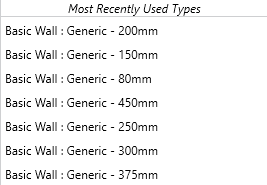
Here are some of the different walls that I used 2.2.1, modifying an existing wall family. Since I am building a visual representation of the building I did not have to think about the construction, and therefore used a generic wall with just a single layer; this minimized the polycount of the final model.

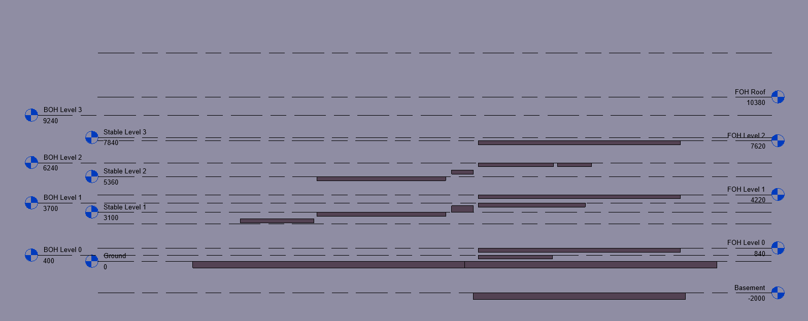
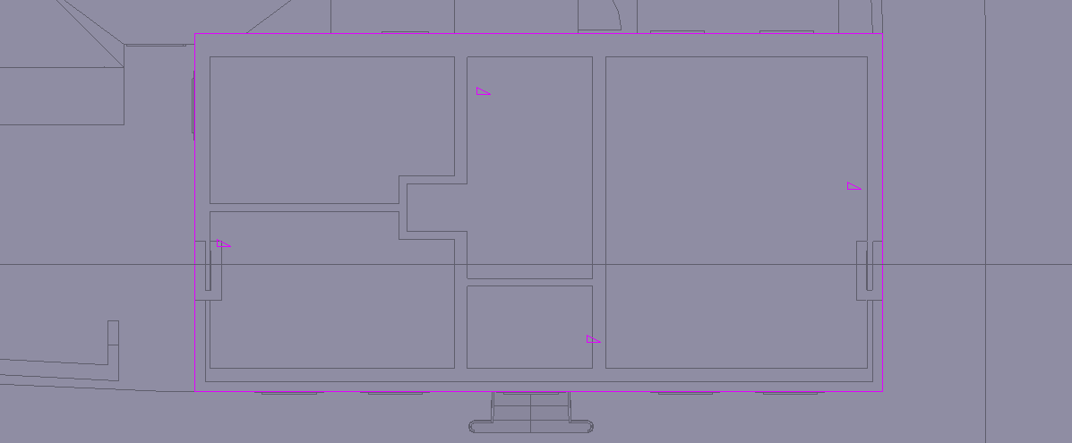
Once I had completed the ground floor walls 2.2.2 and began adding floors, I noticed a problem: whilst the three sections of the house were on different levels, the floor plans were drawn showing them all at the same time. This led to some confusion and time was taken to make sure the floors were set at the correct levels. Even the ground floor is at different heights for each section of the building, with the FOH and BOH being raised. This can be seen in 2.2.3 where the floors have been isolated with the level markers.
Whilst some of the section views were provided which helped to inform the modelling, only two out of the four marked on the site plan were available in the archive. This meant I had to interpret the construction to my best judgement to fill in for the missing information.

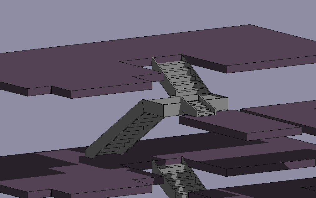
A part of the building that caused confusion was the arrangement of stairs leading to the bathroom from the top floor of the FOH 2.2.4. I could not work out the position of the door, the stairs shown seemed to have no way to connect properly, and the floor heights were extremely different whilst being shown on the same floorplan.
Leaving this part to last helped, as viewing the scene in 3D revealed how the bathroom was connected 2.2.5, branching off the landing in the middle of the staircase. This unconventional design adds a lot of character to the house.
Most of the stairs proved difficult to make whilst following the floor plans. Since there wasn’t a default stair type that fit the design, I had to make a few custom stairs by sketch.
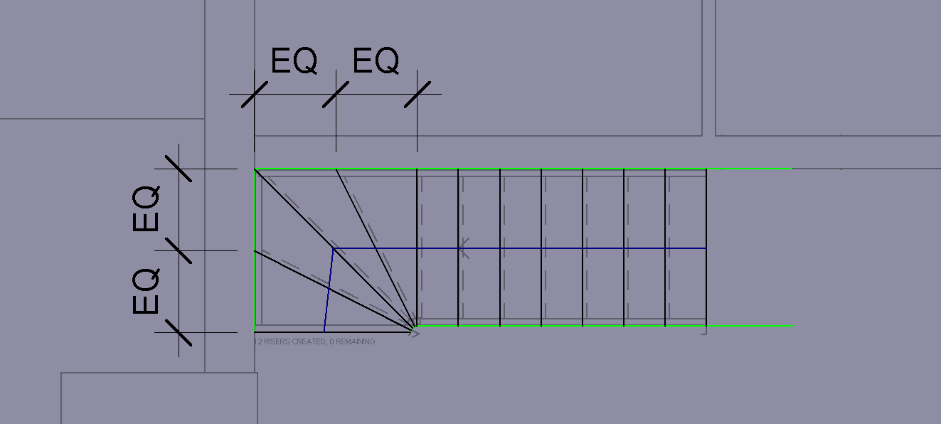
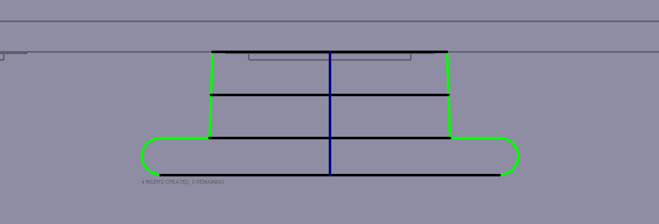
For the interior steps, the hardest part was fitting the steps evenly around such a tight corner. I created a polygon in the stair boundary (green) around the inside corner to evenly space the risers (black) around the corner and used equality constraints to evenly distribute them on the outside of the corner 2.3.1.
The front steps were created with a custom boundary for the rounded, decorative bottom step 2.3.2. Whilst this looked ok, it was remade in Blender later for optimization and design accuracy.
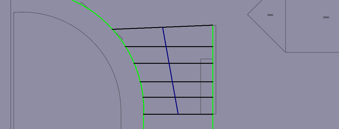
The back steps were also a custom staircase, having to fit around the curved wall on the left 2.3.3. I used edge-select to perfectly match the stair boundary to the curved wall.

With the distinctive tall windows at the front of the building however, I found that there was not a window family that matched them, or their blind equivalents. This led me to learn how to create a custom family.
Whilst I could modify an existing family, I would have to learn how all the constraints and variables were set up before being able to modify it. This also carried the risk of constraints working against each other since Revit does not show all the active constraints or give the option to add or manage them specifically like other CAD programs. Because of this, I chose to make a new family from scratch.
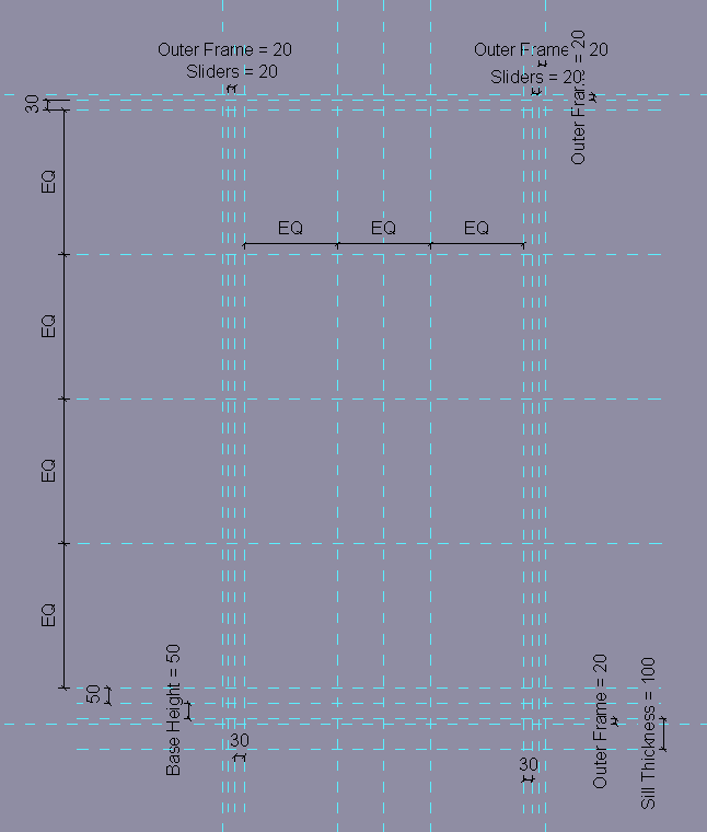
In the window family scene, I began by setting up all the reference planes (shown in cyan) that I would need 2.4.2.
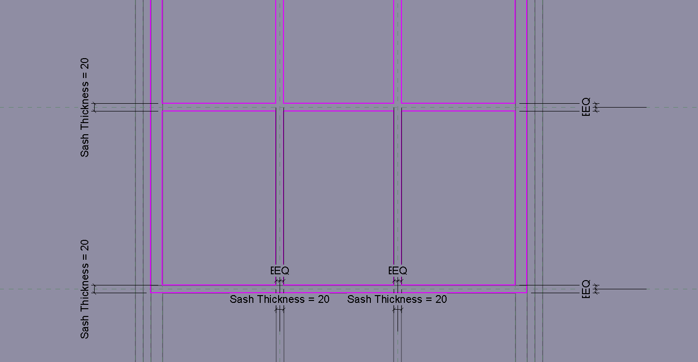
Referencing the plans and photographs of the building, I laid out the framework for the window, adding named parameters for the dimensions that would be able to be modified, and equality constraints to keep the sashes aligned within the window as the dimensions are changed.
I also included dimensions for the windowsill which would be part of the window family. Some dimensions are not parametric; whilst I could have assigned them to be named parameters, I had no reason to change these so kept them constant for simplicity.
The window itself was then made from a series of extrusions using alignment constraints to these reference lines. This meant that they would scale appropriately with the window dimensions. All the drawn components can be seen in 2.4.3.
Within each window sash, I added equality constraints and parametric dimensions around the reference planes to make them adjustable while keeping centrally aligned 2.4.4.
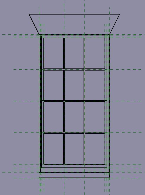
In the 3D view, I set the start and end point of each extrusion to match the design of the window. I made sure to reference the wall thickness where necessary to either change the extrusion depth or location to fit in different walls 2.4.5.

The window was now completed, and very customisable. Through changing the named variables, the window can be easily modified to fit different use cases 2.4.6.

Using the same techniques, I created the blind window and the shorter front window in the same style id.

There are multiple types of roofs on the building. Gambrel roofs at two different levels on the stables, gable roofs at the back of house, and a half-inverted hip roof at the front. Some of these are decorated with dormer windows, using examples of both flat and gable roofs.

The FOH had the easiest roof to construct in Revit. Since the outline is rectangular and it matches the wall edges of the main building, it was a simple matter of selecting the outline 2.5.1.1 and specifying the parameters – angle of 45° and cut-off height, then allowing the program to create the roof 2.5.1.2.

To fill in the gap, I created another roof to complete the shape 2.5.1.3, then set the angle to -45° to invert it 2.5.1.4.

The stable has gambrel roofs, which have two different gradients. For the lower section, I created a roof by extrusion and drew the cross-section shape of the roof 2.5.2.1.

This is given thickness by roof type, and length by extrusion distance 2.5.2.2. I changed the edge trim type to give the roof a flat bottom edge.

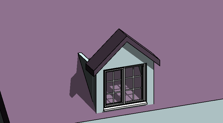
The first step to creating a dormer window is to lay out the walls to define the outline and position. To this I added the gable roof and window 2.5.3.1.
Since the side walls are intersecting with the roof, I edited the wall profile to sit properly in the space 2.5.3.2.
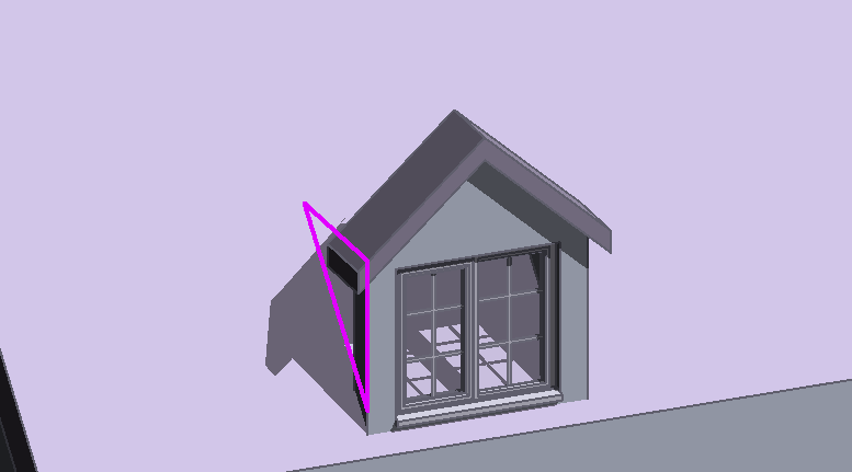
With the wall triangles fitted and roof extended back to meet the main roof 2.5.3.3., the main body of the dormer window is complete.
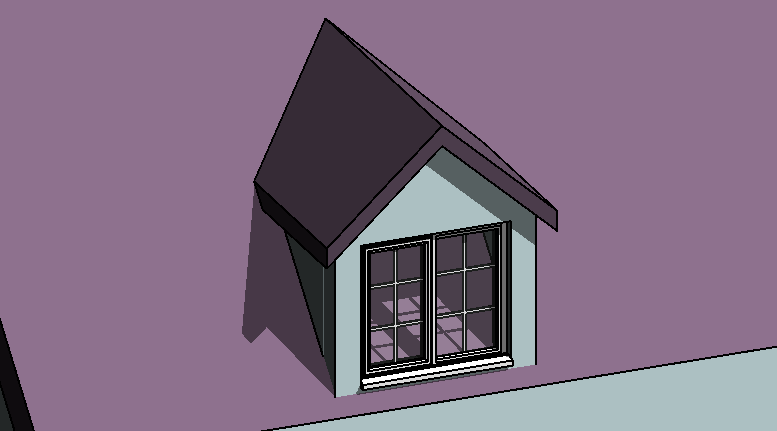
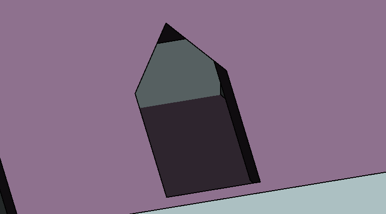
With the dormer complete to shape and dimensions, the final step is to cut the hole in the roof to house it. The program has a tool dedicated to this use, which can be used to select all the elements of the dormer window to shape the cut-out 2.5.3.4. The roof with the dormer hidden can be seen in 2.5.3.5.

With the main block-out complete with walls, roofs, doors, windows and stairs, the model then needed to be detailed. This would mean converting the model from parametric to a polygon model. I chose to export to the FBX file type which is accepted by a large proportion of polygon modelling programs, and which I could use to make small adjustments and add details ready for render or game engine.
The base model block-out was now complete in Revit, and I chose to import the model into Blender to finish it off. This was for a few reasons: Firstly, the I could optimise the model and adjust the topology manually. Secondly, UV maps and materials could be created to apply textures. Thirdly, small details can be more easily created in Blender, since it is a polygon modelling program.
I began by optimising the block-out, reducing the polycount and simplifying the geometry to make it easier to edit and detail later.
Curved faces contributed a lot to the polycount, so elements such as railings and door handles were deleted, dissolved, or recreated to a more appropriate level of detail.
The roof, which had been created from multiple sections in Revit had particularly complex topology, especially at the points where different sections joined together.

The roof joint between the stable and main building 3.2.1.1 shows some of the unnecessary geometry, as well as the disconnected sections.
I initially began by trying to remove excess geometry and create a simplified object, but soon found it to be easier to recreate the roof from scratch. Using the vertex snapping tool to match the shape of the original roof, I recreated the shape as a single object 3.2.1.2.

This meant seamless connections between roof sections and no unnecessary geometry, all within a single object.
I also simplified the wall topology, though this mainly consisted of dissolving edges on flat faces that did not have any use. This is caused where walls join other walls or floors in Revit; the program creates an edge where they join even though it does not affect the shape in any way.
Whilst doing this, I fixed some z-fighting between floors and walls – usually where doors have cut into a wall. This is where two faces are at the same level, and therefore the renderer does not know which to draw on top 3.2.3.1.

I fixed this by adjusting the topology so that there are no visible instances of faces intersecting 3.2.3.2.

Another problem with the walls from the Revit export is the curved wall at the back. It has exported with lots of unnecessary topology creating 599 faces 3.2.4.1.

This is another element of the house which I recreated from scratch rather than trying to work with what was given. The remade wall is formed of 76 faces 3.2.4.2.

The inside floors that followed the walls were simplified and adjusted to fit with the curve.

With the block-out completed 3.3.1, I added basic materials to the building to better visualise how it should look. I created these by using images from textures.com, feeding them through colour ramps into various inputs in the Principled BSDF 3.3.2.

This node setup allows control over the reflectivity and simple bump and specular. The colour multiply node allows easy adjustment of colour, which I used to make more appropriate colours and to create various tints of brick.
This created more realistic materials that would react better to lighting in the renders, making the faces seem less flat. This is not as accurate as a full PBR setup, but at a distance this is not important 3.3.3.

I went through each part of the building adding detail to the block-out. The following section shows some of the different elements.

The basement also has blind windows to maintain the even positioning, and the lower trim has been modelled 3.4.1. The vent material was created with a modified brick texture.

The chimney shape has been adjusted and pots modelled. The gutter pipes and decorative trim also line the building 3.4.2.1.

The stable doors, frames and windows have been recreated 3.4.3.1. Interestingly, the windows above the doors either side of the stable are not symmetrical, the one on the left having a flat top where it meets the hayloft door.

Decorative arches frame the stable yard; even a bricked-up example has been constructed on the left to preserve symmetry 3.4.4.1.

The front-door steps and railings have been remodelled from scratch 3.4.5.1. The point where the steps meet the wall has been modified since the door is inset into the wall.

The decorative door surround makes the entrance appear a lot more extravagant 3.4.5.2. The lamp bracket and lamp are seen to the side.

The windows – especially those with a curved top edge – were re-created in Blender to an appropriate polycount 3.4.6.1, and whilst the curve does not appear perfectly smooth up close, this is fine for the intend use. Decorative one-off windows such as the large ones at the back of the house were created from scratch, filling in spaces which I had left empty in the Revit project.

This concludes the detailing of number 15 3.5.1. The small details such as gutters and trim really bring the model to life and make it look realistic.
I also modelled number 16, as progress towards modelling the whole of Kingsgate Street. This is for visual context and to fill out the scene, so would need to be externally detailed but the internals are not of great importance.
There are no plans available on the council planning archive, but I can compare the relative dimensions to number 15 and make sure everything is to scale with the map.
I did not create any new materials and used the same ones as for number 15 since they are of similar aesthetic and to minimise the draw calls, which would improve render times.
The back of the building did not have any reference photos, and as it is a private property, I could not visit it to see. Therefore, I had no idea of the arrangement or design of windows and doors, or small details. This is not a significant problem since the small details at the back of the building are not very important for the use of the scene, which is an overview of the city. The back layout was modelled using satellite images as reference for the roof plans, but heights, windows, and doors, are all guesswork with inspiration from number 15 3.6.1.
This project was a very good introduction into architectural visualisation and using Revit for the first time showed a new workflow for modelling buildings. I am very happy with the results and think the buildings make a valuable addition to my portfolio and will contribute well to the final scene.