Cherry Hau

Modelling to fit with external components requires careful planning and measurements to make sure everything will be compatible and functional while fitting with the design.
The end goal for this project was to design and create a model which could be 3D printed to house electronic components and contain their wires neatly.

As part of the Healthy Hearts RSA brief, Sinead Marais developed a solution to conveniently and regularly monitor the user’s heart rate to detect potential health problems before they have a chance to develop. The development side and research for the project can be found on Sinead’s portfolio.
To help visualise and test the idea, a 3D prototype was wanted. This would be in the form of a 3D printed replica of a tap handle, with the appropriate additional design elements to incorporate the electronic components comfortably.
I began the project by talking with the client to decide on the design of the tap handle: the form, aesthetics, and the locations of the electronic components.
The design we ended up agreeing on was a generic round handle with six indentations around the circumference to improve grip, and a thumb sensor would be mounted in one of these indentations. There would also be a small screen, and later, a light sensor, mounted flush in the top of the handle. Inside, there would need to be space for an Arduino board and a small battery.


I got to see and take measurements of the electronic components that would need to be incorporated into the design. I took photos of the components for reference 1.2.1 and made notes of dimensions I would need 1.2.2.
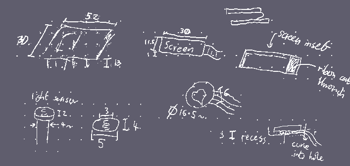
I created a rough model in Blender 1.2.3 to visualise the idea and make sure we were both happy with the design.

We chose to have all the components inset to be almost flush with the face of the tap handle, with the wires going through holes in the tap to connect to the Arduino inside.
I chose to leave a small tolerance around all the components. This would help to account for the inaccuracies in measurements since we did not have access to callipers, as well as tolerances in the 3D printing. Another consideration is that since the model would be tessellated (triangulated) before printing, inside curves may end up slightly tighter than the original design.
To create the model, I chose to use FreeCAD. I chose this program because it allowed me to create fully constrained and dimensioned models. Getting the dimensions correct was important for the 3D printing since I needed to make sure that it could fit with the electronics.
Before I started, I planned out the method I would use to create the handle. Since the shape is roughly round, I chose to use a revolve rather than an extrude to create the main body allowing me freedom to easily change the shape. All the cut-outs would be done with Boolean operations, and then a fillet would be applied to round over some sharp edges to increase user comfort and reduce potential stress points, increasing the strength of the model.
Since the handle is mostly a solid piece, and since the prototype would not be used as an actual handle, strength was not too much of a worry.
I began by creating a sketch of the vertical cross section of the tap handle 2.3.1. I fully constrained the sketch to make editing the shape easier, and so that I had full control over all dimensions.
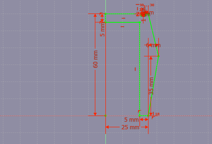
I kept in mind the thickness of the material and made sure that the material is reasonably thick all the way around. The thinnest section is 4mm in the top corner, and I would later fillet the inside corner to spread the stress.
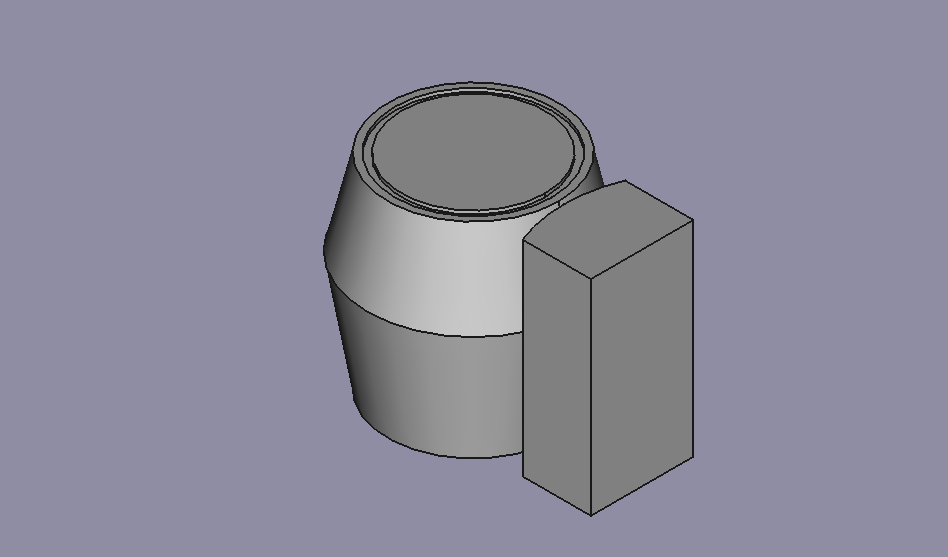
I then revolved the cross section around to create the main body of the handle 2.3.2.

The next step was to create the six grip cut-outs. These are rotationally symmetrical and so I wanted to make sure that I could edit them all from a single sketch.
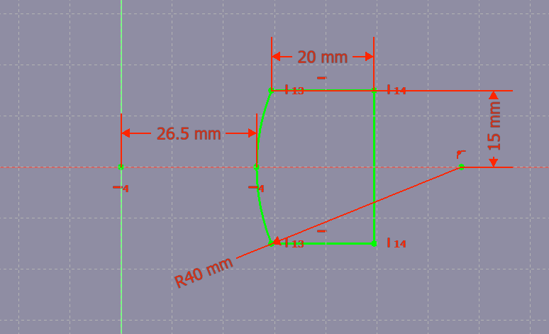
I began by drawing one of the cut-outs in a sketch from the top view, once again making sure it was constrained and dimensioned in a way to ease editing. Specifically, I made it so that I could easily change the radius of the curve, as well as the distance from the deepest point of the cut-out to the centre of the tap handle 2.3.3.
Using the pad command then gave the sketch thickness in a similar way to an extrusion in other programs, to the full height of the tap handle 2.3.4.
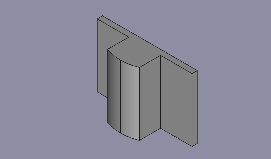
I then wanted to array the cut-out around the centre point using a polar pattern feature. However, I encountered a problem. FreeCAD does not allow a single part to be made up of disconnected bodies 2.3.5.

Since the body would only be used for a Boolean operation and I did not want to have to use six separate operations, I simply extended out the sides of the sketch 2.3.6 to make sure that each cut-out would be intersecting, creating only one body 2.3.7.

Since this extra geometry is outside of the main body of the mesh, they will not affect the outcome.
As I done in Blender, the next step was to use a Boolean operation to cut away the grooves. I modified the radius and distance to centre using the dimensions in the sketch until I had a result that I liked 2.3.8.

The insets were created as sketches dimensioned to fit the electronic components. I had to think about how the wires would be connected through the body of the tap handle, and I discussed with the client to agree on how they wanted the parts to be assembled.
The image 2.3.9 shows the tap handle with all the inset faces, as well as the gaps for the wires to connect through. Since the screen is attached to a PCB with a short ribbon cable and would therefore have to be pushed through from the inside, a larger hole was provided to accommodate this.

I then finished the model using a fillet operation to round over some of the sharp edges 2.3.10. Not visible from this view is an internal fillet to enable the screen’s ribbon cable to wrap smoothly around the corner.

Finally, I needed to export the model to the appropriate format to hand over to the client. We discussed with one of the lab technicians and agreed on either an OBJ or an STL file, as they are accepted for the 3D printer. I also asked about the tolerances in the 3D print, which I found to be extremely precise. This helped me to inform my export resolution.
In FreeCAD, it is possible to work with curves of specified radius and locations. However, OBJ and STL files both work with flat polygons. This means that the model would have to be tessellated, or triangulated, which would convert the curves into a standard polygon model.
After testing a few different settings, I set the tessellation to give a maximum surface deviation of 5.0 µm (0.005mm), which resulted in a mesh of around 70k vertices. This gave a good balance of precision and file size. This was exported as both and OBJ and STL to give the client a backup in the case of one of them failing.
To visualise the tap handle in context, I imported the model into a counter scene in Blender which I had previously made as part of my interior visualisation project. This resulted in a realistic render which shows how the product might look in the setting in which it would be used 3.1.

The tap handle was successfully 3D printed 4.2 and all the components fit flush with their wires and connections comfortably fed through their channels into the middle as designeds.
My biggest worry was a recess being too small to house the component, or for the cables to be awkwardly positioned in the cavities but the good planning and accurate modelling made sure this was not a problem in the end.
This project reinforced the importance of planning and making sure I had all the information required before starting. Working with the client and having to design something to fit with existing equipment was also a new and interesting challenge.
Back to Contents