Cherry Hau

Learning the basics of 3D modelling in Blender by creating four generic assets from scratch, then compositing them into a fully lit scene in a short animation.
The end goal for this project was to create four low-poly assets and render a 30 second animation showcasing the assets that have been created. This is my final product from this project.
As an introduction to 3D modelling, I was tasked with creating four stylised low-poly assets, and then arranging them into a small scene. Through completing small modelling tasks throughout the semester, I slowly developed basic skills within 3D.
I will be delving into each of these sections within this article.
Before choosing which assets I wanted to model, I began by sketching out many different objects 1.3.1. This developed my ability to imagine how each model’s form would look and be constructed in three dimensions, rather than just seeing their 2D shapes on the page. This also helped me to consider the edge flow of models before starting modelling, and to consider which parts of a model may be non-manifold.
This meant that I always had a plan of how I would attempt to start modelling, and knowledge of alternative methods that I could use so that I would never be stuck not knowing how to proceed.
From these sketches, I chose four that could be used in a game as generic assets: a hatchet, a crate, a rowboat, and a vase.
I took this task as an opportunity to try and use many different features within the program, and made each model in a completely different way, by using different modelling techniques and different modifiers.

My first model was the hatchet 1.4.1, and for this model I followed the example workflow, blocking out the model with simple subdivided cubes, and then using polygon modelling to add detail.

My second model was the shipping crate 1.4.2, and in this I started using different modifiers. Through this model I learnt how to use the Mirror modifier, and the Edge Split modifier with smooth shading. I also used the Lattice modifier to add interest and character to a simple model.

For my third model, the rowboat 1.4.3, I used multi-use meshes for the first time, and used the mirror object property in the Mirror modifier. I also baked a normal map for the first time.

Finally, for the vase 1.4.4, I used an almost completely modifier-based workflow, using Screw and Solidify modifiers for the body, and then Array and Curve for the handles.
As I was working on these models concurrently, I learnt new skills while modelling and applied what I had learnt to the other models. This resulted in each model being constructed by similar methods.
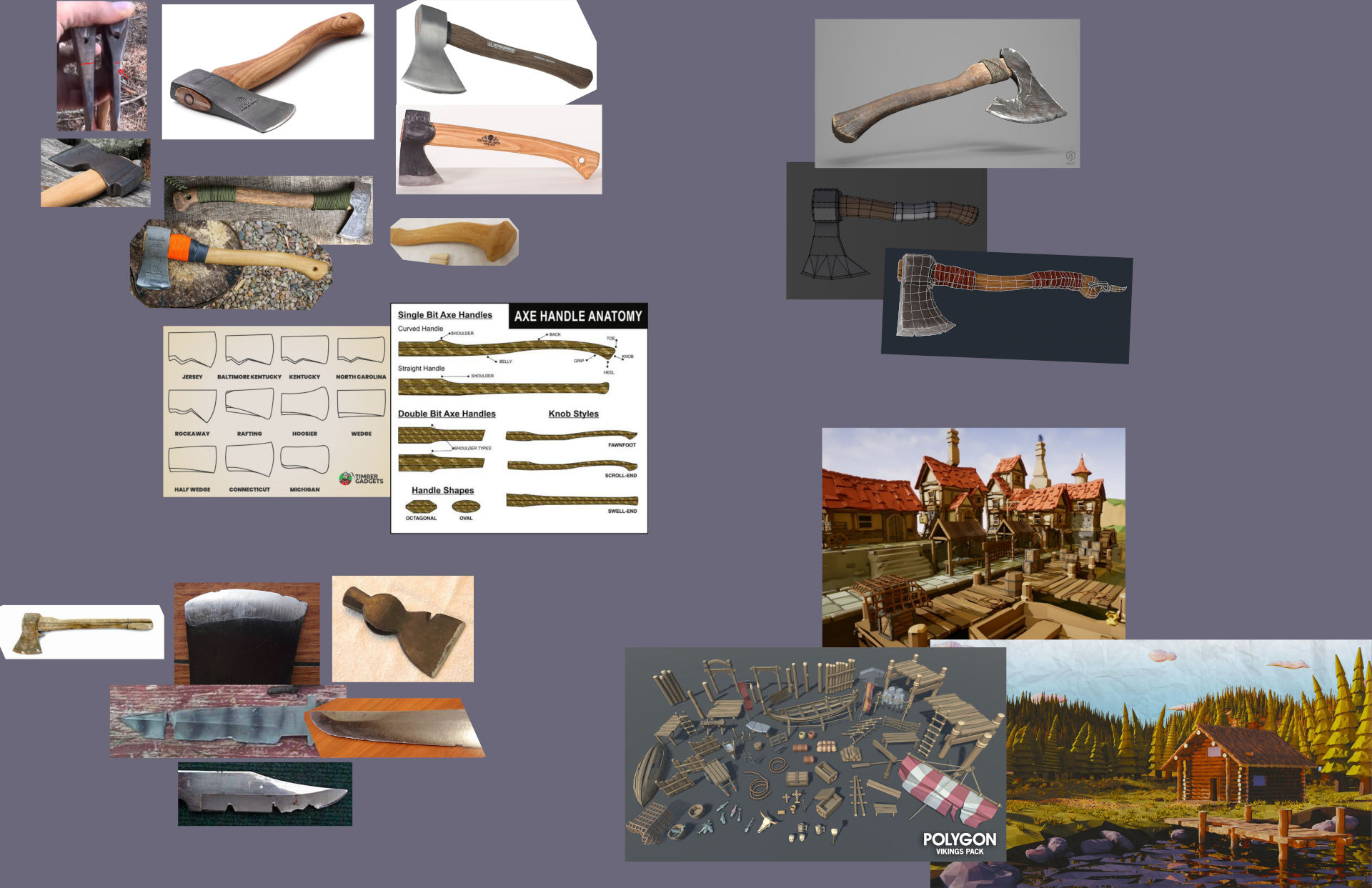
I began by creating a PureRef board of reference images 2.1.1, with references for the form in the top left, style in the lower right, and damage in the lower left – both to hatchets specifically and to various other metal blades. I also took some references of modelled hatchets to look at the topology.
I read up about hatchets uses and their form. The form of the handles seemed to vary with different shaped shoulders, grips, and knobs, with there being straight and curved variants. I decided to model a curved handle hatchet for additional visual interest, along with an exaggerated shoulder.
The head shapes varied greatly and seemed to be dependent more on their origin rather than their intended use, though they mostly had a finer taper to the sharp edge towards the handle to make them more effective at splitting wood. They were secured by a wedge driven into the top of the handle above the head.
Hatchets tended to be very durable, and as such rarely took any significant damage. Signs of use include the sharp edge of the blade not being completely smooth, as the blade was not sharpened completely straight. There was no evidence of large chips in the blade, however there were small, rounded nicks, likely from striking metal or other harder materials when chopping.
The handle, being short and stubby, is also quite robust, though could incur splitting along the grain of the wood, especially from the knob.
Smaller details included paracord or wraps around the wooden handle, and a debossed or printed on logo on the head. Some heads had a notch in their underside, which was used to pull out nails.
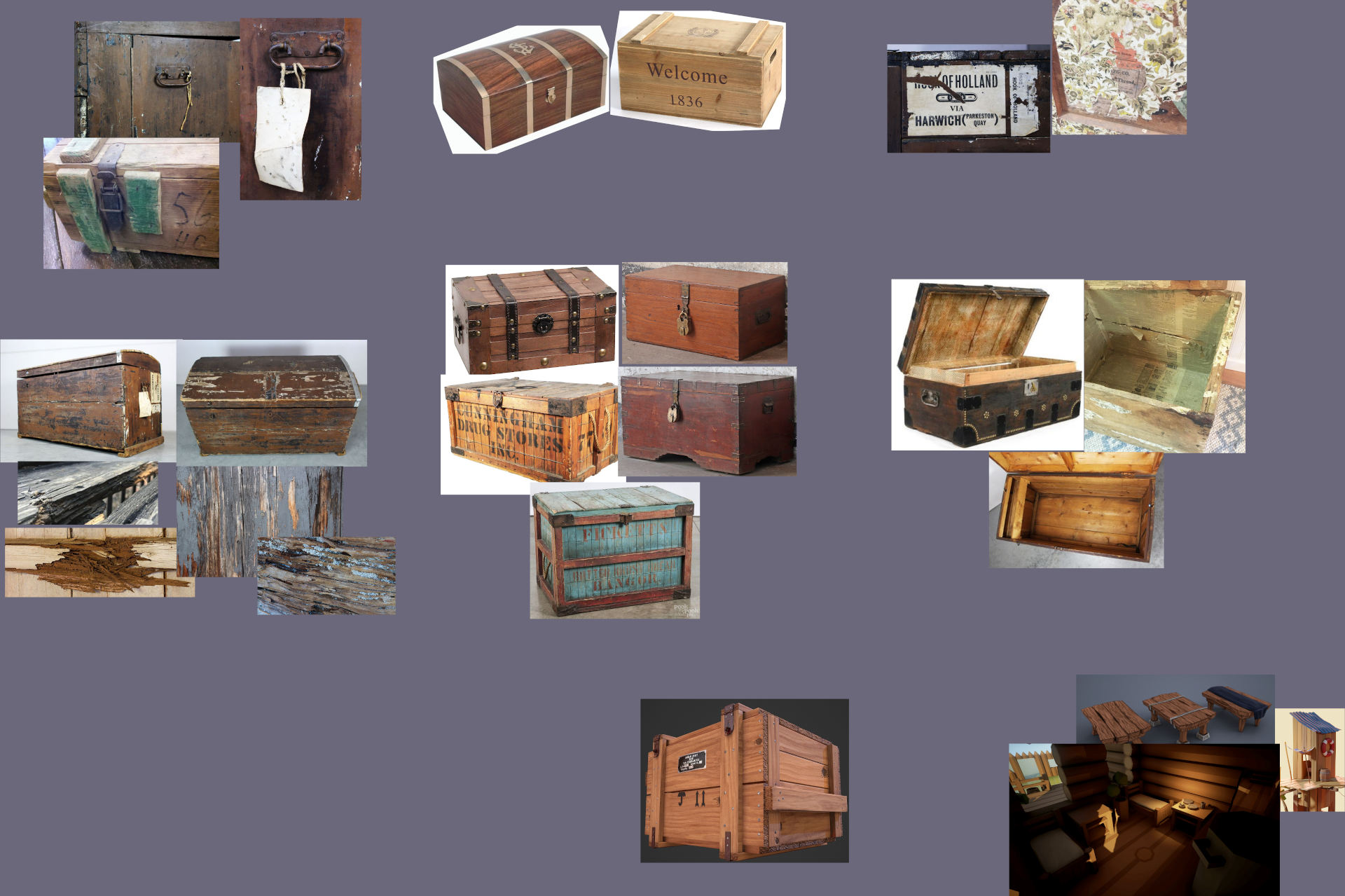
From my reference board 2.2.1 I saw that most shipping crates had a rectangular form, as they were required to stack together. They often had corner protectors and some rails on the top which seemed to protect the crate while they were stacked. Most seemed to be made up of planks of wood all in the same direction, held together by a frame or straps that surrounded the entire crate with braces along the sides and front.
In the middle are generic crates of different designs and with different features, such as the layout of their bracing and latches. In the top left are detail images of handles and a latch, and in the top right are shipping labels. To the right show some examples of the interior of the crates, some of which are raw wooden planks, and one which was lined with newspapers.
I also collected photos of damage in the bottom left, both to crates and to wood in general. Common damage was splitting down the length of the grain on the vertical edges of the crate, and less often on the top and bottom.
Other than that, there was sometimes splitting in some planks, though this was rare. Most of them simply had small scratches along all the sharp edges.
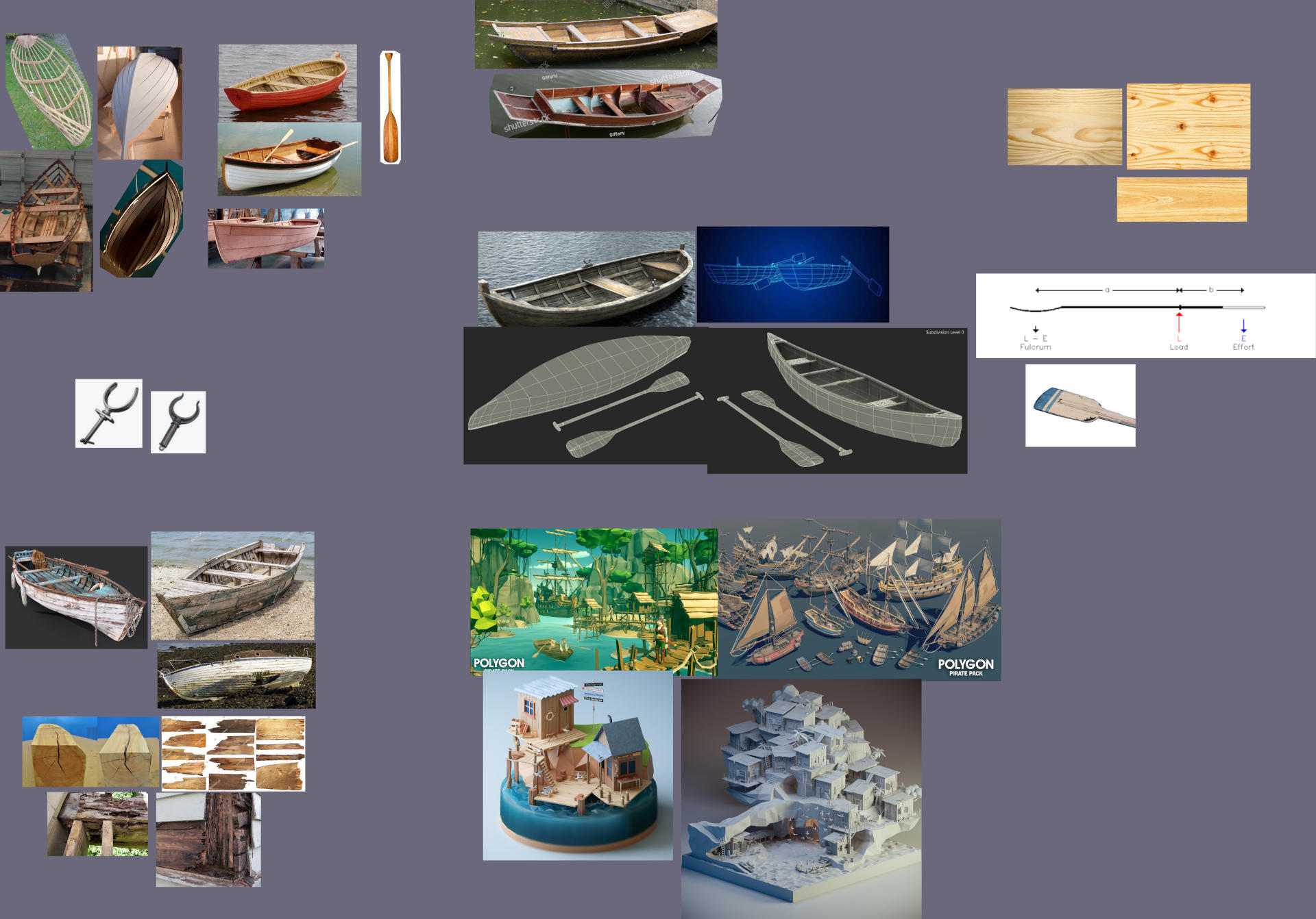
There is great variety in the hull shapes and sizes of rowboats. There are flat bottom Dory hulls and V hulls amongst others, and while the shapes affected the characteristics of the boat, choice of shape seemed to be based on preference rather than intended use or era.
Location of origin seemed to have little impact as well, with different shapes and variations from the same place. There were lengths from four foot up to over 15 foot of each design, with the longer designs more stable and intended to be used in the sea.
Traditional construction was a wooden frame with steamed and bent planks making up the length of the body of the boat, which were then nailed to the wooden skeleton.
As with the others, I gathered relevant images in a PureRef board 2.3.1 In the top left are images of the hull shapes, and wooden frames which help visualise the 3D shape. Towards the middle are some modelled examples with wireframe renders which give inspiration for the topology. Towards the bottom left are examples of wear and damage, both in boats and damage to wood in general. I also collected some images of oars, wood materials, and full scenes for style reference.
Most of the damage obtained seemed to be, as usual, along the sharp edges, and along the hull where the boat had impacted with the ground, potentially when being beached or in shallow waters.
Other than that, natural wear over time of the finish below the waterline was common. For boats that were in use, rot was very uncommon, and would be cut out and repaired to keep boats seaworthy.
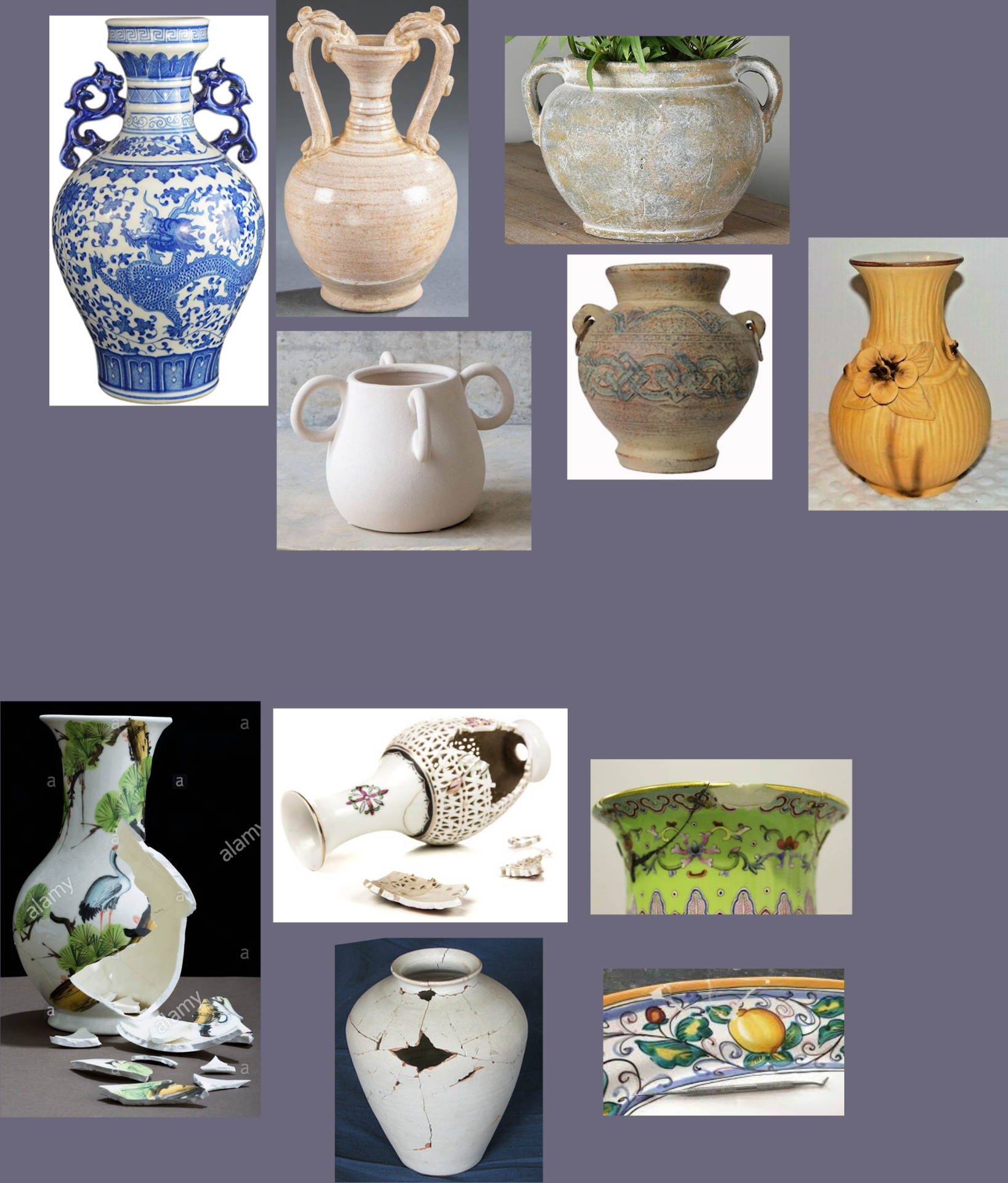
From looking at different decorative vases, I found that I could have almost complete creative freedom of the design. I collected a few unique examples into a PureRef board 2.4.1
There were certain common features, such as mostly being completely round, and those that had handles usually had two, though of course there are exceptions.
Vases, being extremely brittle, rarely took any damage other than light scratches before being completely broken, at which point they shattered around the point of impact into large segments. The only damage taken before breaking was chipping to the varnish over the paint on porcelain vases or fading and scratches to the colours and designs on stone vases.

I began by sketching out basic shapes, before planning how the model would be constructed. I decided to make the model non-manifold in three separate parts, as the pieces would be constructed separately in real life, and as such sketched each part with a rough idea for the topology 3.1.1.
It is not always a good idea to break a mesh into separate objects as they are in their real-life counterparts. This can be seen in some of the other models in this model pack. In this instance however, it made the most sense to break up the model as it is with a real-life hatchet.
I combined features from different shaped heads to add interest to the model, a sharp curve at the top and bottom of the head and an additional curved section where the head meets the handle.

I then made a detail sketch 3.1.2, with views of the proportions from the front, back and side, of which I would base my model.
Having drawn plans that were not in perspective made it a lot easier to model, and to keep the proportions looking even.
I started planning the crate differently, by drawing different very basic forms 3.2.1. This allowed me to experiment with my imagination and try many wildly different designs.


From this I combined my favourite features. I really liked the character of sketch E, and the rails in sketch D hinted at its use of being stacked with similar crates which added to the story of the crate.
I decided that the mesh would be non-manifold and would be comprised of many separate parts for the handles, hinges, and lock, which I then sketched out 3.2.2. This would make it easier to model and animate and would keep the poly-count lower. This is because there would need to be a greater density of detail around hinges and the lock compared to large flat areas such as the planks.

I finally drew out my design of which I would begin modelling 3.2.3 from three angles, which would make it easier to model from.

As I was focussing on the smaller details in these sketches, I kept the shape of outline completely rectangular as it was easier to draw and read from to model. I also omitted the rails, as they would be simple cubes that I would fit in where they looked appropriate.
For the rowboat, I started by drawing a very simple v-hull boat 3.3.1.

However, I saw that many of the proportions were incorrect, and the curves did not appear natural. I iterated on the design 3.3.2, creating smoother curves along the bottom of the hull, particularly towards the stern, where I left the middle section of the frame as a rudder.
I also improved on the general shape of the gunwale, making it a smooth curve rather than completely flat so that the shape looked more organic, and so there were not so many parallel lines pointing down the length of the boat.
As I was concentrating on the modelling techniques for the vase, I decided to keep the design simplistic. I drew out some basic shapes and tried a few different handle designs 3.4.1.

Originally, I planned to make the mesh as a single object, but as there would need to be a higher vertex density around the handles, I ended up making the mesh non-manifold. This also made it easier to edit the overall form of the mesh as I could leave the modifiers unapplied until UV-unwrapping.
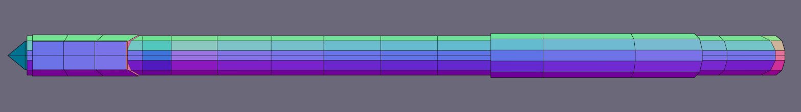
Following my sketches, I began modelling by blocking out the basic shape of the handle starting from a cube and extruding out faces 4.1.1.

From this I had a good idea of the complete shape of the handle and used it as a reference to scale all the other components from.
When starting a new model, it is often a good idea to block out the mesh. This means to simply layout the basic shape of the object, often by scaling and extruding out a cube. This helps to visualise the object in 3D, which lets you check the scale and proportions before detailing the model. In this stage, the mesh is so simple that it is easy to make quick and large changes to the overall shape of the object.
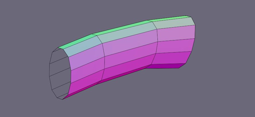
I then went about rounding the handle. I chose to do this by using the bevel tool on the lengthwise edges to round them over, which I then scaled in to form the oval cross section of the handle 4.1.2.

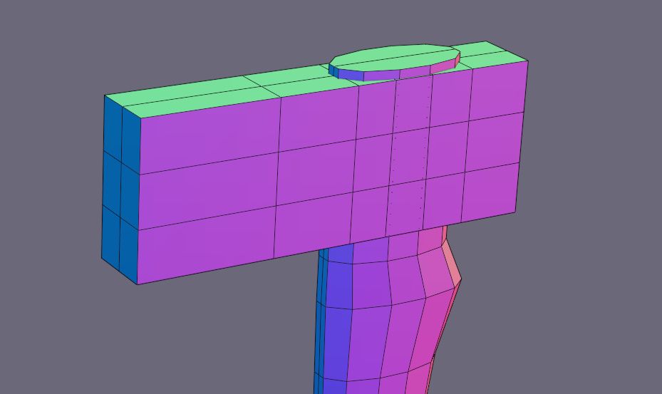
Similarly, I started with another separate cube for the hatchet head and extruded it in the z-axis 4.1.3.
I added edge loops into the cube where more detail was required, then used proportional editing to form the top and bottom curves and general shape 4.1.4.
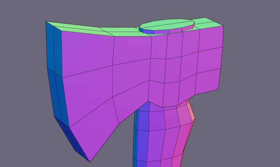
I then created the taper on the blade, by using the Edge Slide command. I also formed the thicker section around the handle 4.1.5.
As I started with a subdivided cube, all the faces were kept as quads with good edge flow so there were no shading errors, and I made sure to keep all the top and bottom faces flat where they tapered off into the point of the blade.
For the grip, I duplicated some faces from around the handle 4.1.6, an used the grab tool to move the ends back into the correct size for the handle. I then scaled it up and filled the top and bottom faces 4.1.7.
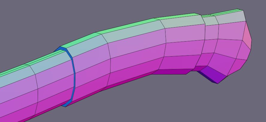
From feedback given in class, we decided that there were too many straight lines all pointing down the length of the handle. This meant that the form of the object lost definition and interest when viewed from the back 4.1.8.

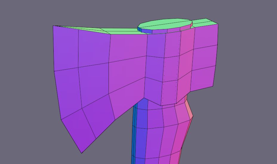
I went back to my sketches to think of possible ways to break up the straight lines of the handle 4.1.9. I decided to reshape the back of the head to an hourglass shape, and to scale out the middle of the head.
These opposite shapes help to emphasise each other. I also exaggerated the width of the handle around the shoulder and grip and thickened the knob dramatically.
I modelled this into the mesh with simple polygon modelling, scaling edge-loops along the x-axis and manually moving elements 4.1.10.
I also added a piece of loose tape stick out from the side of the grip, which made the shape less symmetrical and appear more organic.
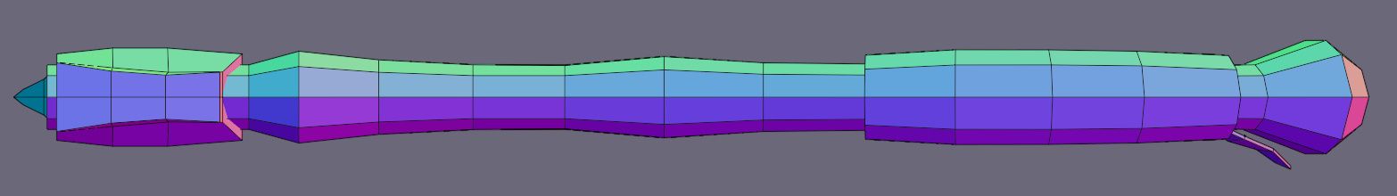
This gave a lot more visual interest from the back and meant that the model now had definition from all angles.

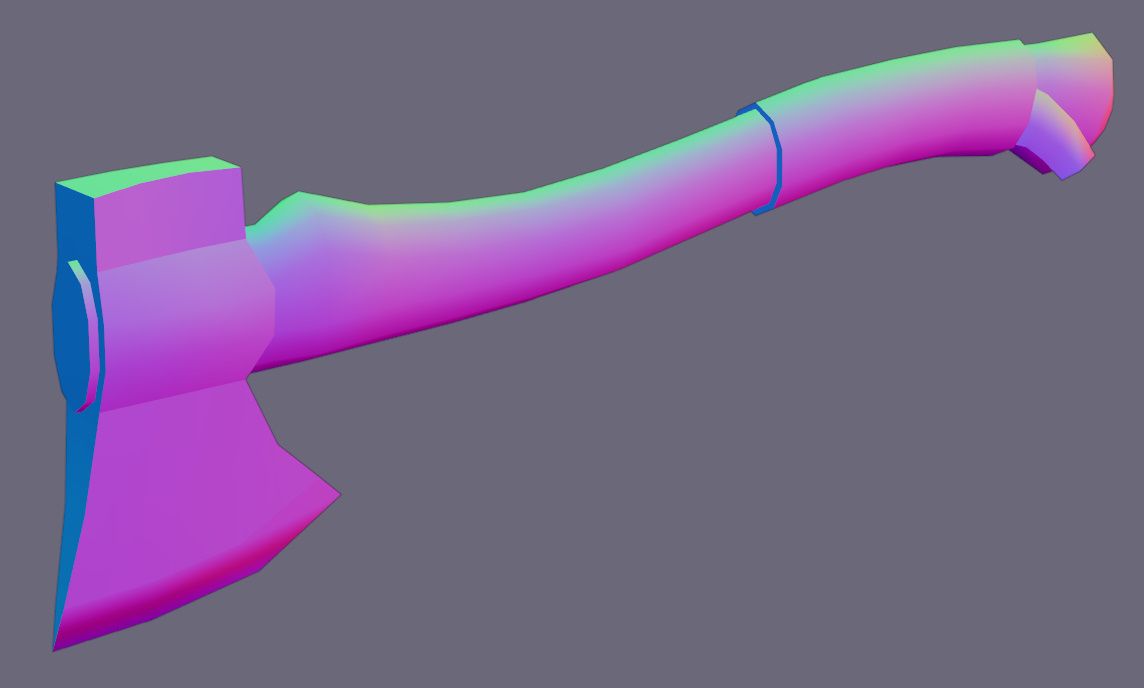
The base model was now complete 4.1.11, and I was happy with how it looked. However, all the edges were visibly sharp. To fix this, I used the Shade Smooth command from the object dropdown menu.
One of the issues with low-poly models is that all the faces have sharp edges in between them. As the poly-count must be kept low for game assets, it is not possible to add a lot of additional geometry to smooth over these harsh edges.
However, it is possible to set smooth shading on an object, in which the vertex normals are averaged between all faces around the pole. This makes the model look smooth all over, while keeping the good performance of a low poly-count.
This smoothed over the entire model however, and definition was lost around sharp corners as the shading attempted to make them look smooth. To retain definition in these areas, I had to tell the software which edges I did not want to be smoothed. I did this with the Edge Split modifier.
Sometimes you may want to keep some sharp edges while smoothing over others. This can be achieved by using Smooth Shading with the Edge Split modifier. This stops the smooth shading from applying to specific edges, while still applying it to others.
For basic applications, you can enable the Edge Angle checkbox and it will automatically sharpen edges that are sharper than a specified angle that you can change. However, to fine tune the modifier, you can also manually mark edges as sharp from the edge menu, and this will give you total control over which edges appear smooth and which are kept sharp.
This meant that the slight angle changes down the length of the head and handle were shown as smooth, which emphasises the cartoon like look, and sharp edges were only on the edges where they are needed 4.1.12.
I decided most of the detail would be textured onto the model. However, the damage to the blade would have to be modelled into the mesh. I did this by using the vertex bevel tool on the edge of the blade, then deleting the faces and filling in the gaps 4.1.13.

As this broke the edge flow around the blade, I made sure to duplicate the undamaged model as a backup. I added a few more chips using the Knife Tool.
I unwrapped the mesh by marking edges as seams along the length of the handle, grip, and head. this allowed them to unfold neatly onto the UV map.

I used a UV grid 4.1.14 to help make sure all the UVs had no stretching and were appropriately sized. I found that it helped to imagine that it was a piece of paper being folded, and any awkward creases would lead to stretched UVs.
Once I was happy with the UVs, I scaled and moved them to fit into the texture area 4.1.15.

I exported the UV layout into GIMP for texturing, where I drew out a basic texture using the UV layout as a guide. I applied this by using an Image Texture node in Blender, which I connected to the primary colour of the principled shader 4.1.16.

The hatchet was now completed 4.1.17. I am happy with the outcome of this model, and I learnt a lot while making it. I was not completely satisfied with the texture, and I switched program from GIMP to Paint Tool SAI to create textures.
Like the hatchet, I started by blocking out the basic form of my crate 4.2.1. In this case, it was simply a scaled-out cube to the dimensions that I wanted the final model to be.

I realised that parts of this model would be entirely symmetrical in all three axes so to help achieve this, I used a Mirror modifier with all three axes enabled. This meant that I only needed to model one corner of the crate and all the others would be generated automatically. This is a very useful modifier because it allows me to visualise changes in real time while editing quickly.
When modelling an object that is symmetrical, it makes sense that you should only have to model half of the object, and the other half can simply be reflected. This is good for the workflow as changes to one half will automatically affect the mirrored portions.
This can be achieved by using the mirror modifier, which can reflect a mesh around a point of your choosing, and in any axis. By default, this is around the object origin, though can also be reflected around a separate object.
I continued blocking out the model 4.2.2, adding the frame and the rails.

I realised that some of the details in the crate, including the handles, and rails, were not symmetrical in the z-axis. This meant that for these parts, I could only use the Mirror modifier for the x and y axes.
What I did was separate the corners and frame from the rest of the mesh, as they would continue to be mirrored on all three axes, and then apply the Mirror modifier in the z-axis on the body. This would allow for the easiest editability.
Some of the benefits of using modifiers including avoiding repetitive tasks and speeding up modelling. One of the best things about modifiers is that they are non-destructive, and the base mesh is left unchanged.
However, sometimes it is necessary to override a modifier so that you can change a section of a model. This can be done through the irreversible process of applying the modifier. This takes the modifier’s changes and applies them to the base mesh so they can be edited. It is a good idea to back up your mesh before applying a modifier, as the geometry will almost always get significantly more difficult to edit once the modifier is applied.
I created some corner protectors using polygon modelling and added some basic materials to better imagine how the crate might look once it is textured 4.2.3.
This created a lot of different materials, however, as I had to have one for every colour. As one of the restrictions for our scene was to have a maximum of five materials, I would have to reduce these down later.

I added bolts to each corner with cubes, but I was not very happy with how they looked as they had obvious corners but still contributed a lot of polygons to the overall mesh.
As the crate would be animated opening, I needed to also create the inside of the crate, so I used the Inset Face tool on the top face of the crate to create a uniform edge thickness, then extruded the middle face down to hollow out the crate.
I started adding in small details like the handle, hinges, and lock, and modified the corner protectors to have a rounder inside curve 4.2.4.

At this point, I decided to draw out different styles of wooden bracing 4.2.5 as I was not particularly happy with how the model was looking.

I decided that I preferred the look of diagonal braces, because while they were uncommon, they helped break up the shape of the model with lines that were not perfectly horizontal or vertical.

I then modified the mesh to fit with the new sketch 4.2.6, and much preferred the look of the crate, so decided to stick with the diagonal braces.
At this point, the base mesh was mostly complete. Before adding damage, I decided to UV unwrap the mesh. I did this the same way as the hatchet, by marking edges as seams then unwrapping.


If I saw any obvious distortions in the UV map, or on the mesh by using the UV grid 4.2.7, I simply added more seams and unwrapped the mesh again. Using the UV grid, I then resized each UV island to get a uniform texture density on the mesh and arranged them to fit in the texture space 4.2.8.
While the first model I experiment with baking normals on was the rowboat, I really improved my technique on the crate. As the shipping crate is a very simplistic model, it meant that I could experiment more easily with adding detail in other ways, through textures and normal maps.
In a game asset, it is of utmost importance to keep the models optimised with as low a polycount as possible. However, this does not mean that fine detail should be sacrificed. Of course, one way to do this is to draw on additional detail into the texture map, but a way to imitate additional geometry is to use a normal map.
What a normal map does, is it treats the material of the object as if it is facing in a different direction to the normal of the face the texture is on. What this means is that lighting and reflections will bounce as if the face was not completely flat. This means that additional small details can be convincingly portrayed while keeping the poly-count of the asset the same.
As a normal map is using texture space to portray a 3D direction using the red, green, and blue channels of the image texture, it is difficult to understand and edit manually. However, through baking the normals in Blender the program can generate normal maps automatically from another mesh.
With the low-poly mesh duplicated, I began adding details such as nails to the corners, hinges and latch, and gaps where different planks met to form the walls of the crate 4.2.9. I also created a more interesting, curved shape around the lock, and rounded off details such as the handles. Where there was shared texture space, I only needed to create a single version of that part.

This left me with a much more detailed model, albeit with a much higher polycount. However, I could now bake these details onto a texture that I could then apply to the low-poly model.
I then switched render engine to Cycles, which is required to bake textures, selected both my high and low poly versions of the mesh and baked a normal map. While a lot of the detail had been transferred well, places where there was shared UV space and intersecting geometry had strange artifacts 4.2.10.

This is due to faces on the low poly mesh not knowing which face it was targeting on the high poly mesh, leading to shading errors. I decided to fix this by separating the high and low poly meshes into different parts that were not intersecting and baking their normals separately.
I did this by selecting parts of the crate with the select linked command, and then using the separate command to split them off into separate objects.
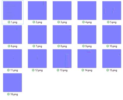
Previously, I had saved each normal map as a separate image N1 and combined them afterwards in an external image editing software.
After researching for a better way, I found that I could switch off “Clear Image” in the Output section of the Bake settings N2, which meant that each successive bake would be added onto the previous normal map.
This saved a lot of time, as I did not have to manually mask 16 separate normal maps.
After baking each part separately and combining them into a single normal map 4.2.11, there were no more artifacts or errors.

The benefits of using a normal map can be seen in the detail to the planks of wood making up the length of the chest 4.2.12. While lines could be drawn on using an albedo texture, combining that with the normal map makes it react with the lighting, and makes the face feel as though it is not completely flat. This is while keeping it all as only a single quad, or two tris.


While keeping the poly-count the same, the normal map adds a lot of additional detail to the model. This is great for game assets or for animations, in which the render time must be kept as low as possible.
Like the hatchet, the most obvious visible damage was splitting along the grain of the wood, particularly along the edges of the wooden braces and outer frame.
I created these by adding an edge loop around the component, then selecting and bevelling one of the vertices on the outside of the loop, creating a cutaway in the plank. I then moved the vertices along the length of the plank, to better look like the wood had split 4.2.13.

As smooth shading is enabled, I had to make sure to mark the edges as sharp so that it looked like a piece had broken off.
This created a quad that was not flat. This can be remedied simply by triangulating the face. I did this by choosing where I wanted the crease to be and selected the two vertices on either side of the crease. I then used the join command to create an edge between the two vertices, eliminating the shading issues.
Using the UV layout as a guide, I drew out a texture inPaint Tool SAI content, starting with base colours and then adding detail on a layer above.

I exported the texture and added it to the material in an Image Texture node.

Now I had a fully detailed mesh, complete with texture, normals and damage content. However, it was still completely rectangular. Now I wanted to add character to the asset.
I chose to do this with a lattice and the Lattice modifier.

Through the lattice modifier, you can create complex and interesting shapes while still maintaining the editability of a simple mesh. By assigning a lattice to the lattice modifier on a mesh, the mesh can be non-destructively distorted.
I began by creating a lattice and positioned it over the crate, then increased the resolution to give more points to work with 4.2.16. I added a lattice modifier to the crate and assigned the lattice to it.
This gave me a cage around the mesh, which I could use to control the deformation of the crate. As with the sketch, I wanted to have an hourglass figure, with the top of the crate leaning forwards slightly.
As the crate would be deformed, I needed to add some extra geometry. I did this by adding edge loops where they would be curved.
Entering Edit Mode on the lattice gives a familiar interface, with a mesh of control points. I used proportional editing to edit the lattice into shape. By using the lattice, it is non-destructive, so the original mesh is still unchanged for editing. It is also a lot easier to modify, as I only had to concentrate on the general shape rather than the intricate detail of the mesh itself.

Following the plan, I created the curves in the lattice, which then deformed the mesh 4.2.17. This gave my simple rectangular crate a lot more character, and a fun cartoon-like feel.

The new topology can be seen in 4.2.18. Only a few additional edge loops were required to cater for the deformation, as it was only subtle.
The mesh was now complete 4.2.19. I learnt how to use a lot of new modifiers whilst modelling this asset and am very happy with the finished model.
I began the rowboat in the same way, blocking out the shape from my reference images 4.3.1. Through this, I found that the boat looked too short and stubby for my liking.

This showed the advantage of blocking out models as I could modify the shape quickly with the simple geometry.

Once I had rescaled my blocked-out rowboat to nicer looking proportions, and to a realistic absolute scale 4.3.2, I began polygon modelling to add detail 4.3.3. The benches and wooden details were added as non-manifold objects as planned.

Once I was happy with the general shape of everything, I refined the shape of the hull 4.3.4. As the additional geometry would make the overall proportions a lot more difficult to edit, I made sure I was happy with the proportions before adding in extra edge loops and smoothing the curves.


I also refined the shape of the benches to look more aesthetically pleasing and to fit to the shape of the new hull 4.3.5.

I then modelled the oarlocks 4.3.6, starting by blocking out simple primitives of a cube and a hexagon, then refining the shape with polygon editing.
I added a Mirror modifier to duplicate the object, but by default it mirrored around the object origin. I set the Mirror Object of the modifier to the boat, so that it would mirror around the origin of the boat instead.
This was a good start, but there were also another set of oarlocks which were in a different orientation so could not also be simply mirrored. This led me to use a linked duplicate.
If you use the same mesh multiple times throughout a model, you may wish to edit them all at the same time. When duplicating a mesh, it usually creates an identical, though separate, object which can be edited independently to the original.
However, there is also the option to create a linked duplicate, which will link the new mesh to the previous. This means that if you were to edit any instance of the mesh, any linked mesh will be updated to match the changes made.
This meant that I could edit one of the meshes in a fixed orientation, and it would update all the linked objects 4.3.7.

This is extremely useful, as it is a lot easier to edit in its local axes when it is upright to the camera.

The base mesh was now complete 4.3.8, and I was happy with the form. This meant that it was time to UV unwrap.
I marked seams along the mesh and unwrapped, viewing it with a UV grid 4.3.9 to identify any areas of distortion or stretching.

Like the crate, I chose to add detail to the mesh with a normal map. I went about this in the same way, by creating a high-poly version of the mesh 4.3.10. I duplicated the low-poly mesh and modified it to add detail, such as the gaps between planks, and rounding over sharp edges.

I then baked the high-poly detail onto the low-poly mesh.


This comparison 4.3.11 shows how much additional detail can be added from a normal map while the geometry remains unaffected.
As most of the damage to the boat would be along the top edge of the gunwale, likely where the boat would have struck another object, I decided to use the same method as the damage with the crate 4.3.12. This created tear-out where the wood would have split along the grain and separated.
I did not want to create too much extra geometry however, as I was still trying to keep the poly-count low. Therefore, I made use of the edge loops that were already present to start each chip.

Due to the curved top of the gunwale, I could not snap the vertices in any axis to move them along the edge. Instead, I had to use the Vertex Slide command, which allowed me to move the vertex in the direction of one of the connected edges.
Finally, I drew the texture in Paint Tool SAI, using the UV layout as a guide overlay. The model was now completed 4.3.13. I am very happy with the outcome of this asset.
In CAD, there are two main ways to turn a sketch into geometry. The first is to extrude parts of the sketch to give it thickness, which is the method I used to create the first three models.
The other, which is less often used in polygon modelling, is to revolve a sketch around an axis, to create a round object with a dimensioned outline. I decided to try to use this method for my fourth model, the vase.
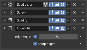
I started this by setting up my modifier stack 4.4.1. I wanted it to be as flexible as possible so tried to make it so that I could use a minimal amount of geometry.
I started by adding a Screw modifier first, which would revolve the geometry around the object origin. I set it to the z-axis and enabled merging. This is a very flexible modifier as I can easily change the number of steps which control the number of edge loops around the circumference of the object as it is revolved.
The screw modifier is very useful for creating cylindrical assets. It can create round arcs of any angle with variable steps. By changing the screw, you can offset the end point to create a spring-like model quickly. Adding more iterations will add more loops to the helix. This can quickly create precise shapes that are difficult to create manually.
I also added a Solidify modifier, to make the vase a consistent thickness throughout. I changed the offset so that the new geometry would all be on the inside of the mesh.
The solidify modifier is extremely valuable, as it is often of use to create a mesh that is of uniform thickness. This is great for hollow objects, or those made of plate materials, as by simply specifying a thickness, it enables you to quickly change the overall shape without having to worry about the geometry of the inside walls. The offset can also be adjusted, which controls whether the thickness is on the inside or outside of the original geometry.
This meant that to make the vase, I would only have to draw the outline, and it would be given a uniform thickness throughout.
As the vase has smooth curves making up its cross-section, I decided to make it even easier to edit by placing a Subdivision Surface modifier at the top of the modifier stack. This meant that it would smooth out my initial curve before applying any of the other modifiers, so would not create any more edge loops around the outside and would not smooth over the rim of the vase.
Finally, I enabled smooth shading on the Screw modifier and added an Edge Split modifier to the end of the modifier stack.


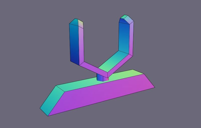
As can be seen in 4.4.2, from only eight vertices, an almost completed model is created. This makes it extremely flexible and can be used to create many different shapes very quickly.

For the handles, I chose to make the design with the vines. To make this, I modelled a segment of the vine with a leaf on either side 4.4.3. I then wanted to duplicate this segment and bend it into the shape of the handle.
After looking at the Blender documentation, I found that I could create a curve in the shape of the handle 4.4.4 and apply modifiers to my vine segment to fit it to the curve.


Firstly, to duplicate the vine segment, I used an array modifier. This modifier duplicates the mesh repeatedly, each with the same transformation 4.4.5. I adjusted the settings to make a consistent vine and enabled Merge by distance.
Secondly, I added a Curve modifier, which deformed the vine segment along the path of the curve 4.4.6.

This meant that it would be easy to change the handle design of both the single segment, by modifying the mesh, and the overall shape, by modifying the curve.
Before it could be UV unwrapped, I had to apply the modifiers to convert the modifiers into 3D geometry.
I then unwrapped the model the same way as the others 4.4.7, but while considering my design. I chose to unwrap the bottom separately, as I had designed leaves to wrap around the bottom of the vase.

For the main body of the vase, I wanted to make it as easy as possible to draw on textures. However, it was difficult to visualise the texture on the model, as the UV island that covers the main body was curved.
As most of the textures I wanted to draw on would be consistent around the vase, small distortions in that direction would not be visible. This led me to use the UV Squares addon to align the points on the UV island to a grid 4.4.8.


While a drawback is that the UV is slightly distorted horizontally, this made the texture a lot easier to edit,
I then drew the texture in Paint Tool SAI to complete the asset. The vase was now complete 4.4.9 and while a relatively simple final product, I learnt a lot how to use a lot of new modifiers to generate geometry.
I decided to create a small, self-contained scene to showcase my assets in an animation.

To fit the theme of the assets, I decided to make a dock 5.1.1 made from basic primitives.
I created the water by using a subdivided plane, which I extruded down to give depth. I created a simple material by mixing a Transparent and Glass BSDF node with the index of refraction set to 1.33, approximately that of water.


To give the water some movement in the animation, I decided to use a Displace modifier in the z-axis to create small waves 5.1.3.
After feeding a Clouds texture into the texture input and assigning an empty object to the texture coordinates, I was able to animate the displacement by moving the empty 5.1.4.
I added a Triangulate modifier set to Shortest Diagonal to prevent the quads from the subdivided plane being distorted.

A problem I encountered at this point was that the water was clipping through the boat. To solve this, I added a Boolean modifier to the water set to Difference and assigned the boat as the target.


This meant that when the boat intersected with the water, the section that was intersecting would be subtracted from the water and would therefore no longer clip through the boat 5.1.5.

I made a lantern for interesting lighting 5.1.6, and some ropes to attach the rowboat to the mooring by using Bezier curves 5.1.7, using a cylinder with an Array and Curve modifier to give the curve depth.

I could have used a bevel in the Geometry tab of the Bezier curve, but that would not have been able to specify texture space to get the material from, so would need to create a separate material. Due to the five-material limit, I could not afford to create a separate one just for the ropes.
While I was laying out the scene, I also got started on storyboarding my animation. I knew that I wanted to spend time focussing in on each of the four assets, showing off some of the features. With such a limited time, most of it would be spent on closeups of the assets so I just needed to plan how I would move between them.
Having the hatchet in the crate gave a good reason to animate the opening of the crate. Similarly, I decided to have the vase on the boat as a cargo, just to integrate the models together.


This naturally led to the order of focussing in on the crate, then opening it and looking at the hatchet inside. I then needed to link it to the boat and vase, which would go together. I thought of having a character pick up the hatchet and put it into the boat 5.2.1, but as I had such limited time in the animation, I decided to use a simple jump cut into a camera on the boat, but with the hatchet placed in the same relative orientation to give the illusion that the camera had not moved 5.2.2.


We were given two restrictions for our scene. No more than five materials can be used, and no more than four lights.

The five materials restriction was a little awkward. As I had created separate materials for each of my four assets, that left only one remaining to use for the rest of the scene. I decided to have the hatchet and vase share a material, as they both had a lot of unused UV texture space. After moving around their UVs and textures, that left me with two material slots for the rest of the scene.
A separate material for the water was essential, as I had no transparent materials in use for any of the assets.
The final material was an Emission shader for the lanterns which were going to light the scene, because that too had to be a separate material 5.3.2.

With such few material slots, I had to share these materials between the remaining assets.
For the ropes tying the boat to the pier and the sand under the water, I used parts of the wood texture for the handle of the hatchet. The pier supports also took from the hatchet handle, and the planks of the pier took their texture from the planks on the side of the shipping crate.
I used the water material for the glass surround of the lantern, and the metal parts of the lantern is also from the shared hatchet and vase material.

As I had planned to showcase the texture detail in the video in transitions, I did not have to worry too much about the clarity of specific details in the scene, and therefore could focus on artistic direction.

I wanted an atmospheric scene, so decided to make it night. I did this with a relatively bright night HDRI with lots of ambient light. I then wanted some additional lights in the scene to highlight some of my assets. I chose to model a simple lantern, to fit the theme of the scene, and used Point Lights inside them with an animated power variable to simulate a candle flickering.
I created a simple camera rig for ease of animation, by nesting the camera within two empties.

The first empty was for controlling camera rotation in the z-axis, as well as the camera target 5.4.2.

The second empty was a child of the first and was used for controlling camera rotation in the x-axis 5.4.3.

The camera was then a child of the second empty and was only animated moving towards and away from the target 5.4.4.

The camera itself would also control rotation in its local z-axis, though I did not plan to use this. By setting up the camera like this, it was easy to change the target of the camera, and precisely control its rotation in the different axes, much like a gimbal in real life videography.
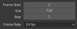
I began by setting the start and end frames on my animation 5.5.1. For a 30 second animation at 24 frames per second, that meant that there would be 720 frames of animation.

I decided to begin by animating the camera movements around the scene.
To speed up this process, I added my camera gimbal to a separate collection and set my active keying set to location and rotation 5.5.2, which meant that I could quickly add keyframes.

In the playback settings, I set the Sync Mode to Frame Dropping 5.5.3. This meant that frames would be skipped if the render took too long, which meant that I could preview my animation at closer to real time speed.
With my camera setup, animating was painless. I could easily move my camera target empty to the item I wanted the camera to focus on and create a keyframe for location and rotation as selected in my active keying set.

Through this process, I took the camera around the scene, taking time to focus in on each of the four assets. I also added a bit of time looking around the scene at the start, where I would overlay my introduction text 5.5.4.
I then went about animating the crate opening. As it was already rigged, this was a simple process of rotating bones to open the lock, then lift the latch and lid. The hardest part of this process was making the lock opening look smooth and avoiding clipping.
To make the animation look smoother, I used the curves editor to adjust the interpolation between keyframes 5.5.5. This gave me more control over the animation.

This took a few attempts as I often ended up with unnatural animation and awkward movements as the lock fell. After a few failed tries and a lot of tweaking, I had an animation that I was happy with 5.5.6.

I decided to render the video to AVI, as I was going to edit it afterwards and therefore wanted less compression. This created a file far too large for web at over 600MB, but as I would export it after editing with H.264 encoding, it would be compressed down later.
After rendering and watching the animation back, I found a few mistakes in the render that I wanted to change.
Instead of re-rendering the complete animation, I changed the frame start and end points in the render settings, and just rendered out the frames that were changed.
This meant that it would render a lot faster and I could simply replace the problematic frames in editing.
I edited this video using Adobe Premiere Pro 6.2.1. Most of the editing is very simple, using linear wipe transitions to reveal image layers above the main video layer, and using highlight colours from my website colour palette.

I created my logo animation at the start using Adobe After Effects 6.2.2. To continue to keep a consistent theme, I replicated the splash screen of my website with my logo rotating to the side as my name revealed itself in a horizontal linear wipe. I also added my pathway of “3D Visualisation” to the intro.

This After Effects composition was then imported directly into the Premiere Pro file, which I exported with a H.264 encoder to an mp4 file.
I tried an export with medium bitrate which gave me a file of around 12MB, but there were visible artifacts in the video from the compression, so I re-exported it at high bitrate. This resulted in a video of around 35MB.
I uploaded this to Vimeo and embedded the player into this website in an iframe container so that it could be watched without having to download the video from the webserver which would be the case with a directly embedded video in HTML video tags.
I am very happy with my completed animation, and think that it shows off my assets well, both to casual viewers and to other 3D artists looking for quality of topology and UVs.