Cherry Hau

Learning character modelling by creating the character Daisy-Mae from Animal Crossing, while focussing on optimisation by keeping a low poly-count and good topology. This project also covered an introduction to rigging and weight painting, as well as setting up inverse-kinematics and animation.
As an introduction to character modelling, I was tasked with modelling, texturing, and rigging the character Daisy-Mae from Nintendo’s Animal Crossing series of games. We were taken through the process step by step, broken up into smaller tasks.
We were told to break the model down into five separate parts: the head, hood, hat, body, and dress. Originally, the plan was to team up with someone and each make some of the parts, putting them together at the end. Unfortunately, my team-mate did not complete any, so I made all five myself.
This was good practice for me, as it gave me more experience modelling and I could choose where to make compromises in mesh resolution across the whole character to meet the poly-count goal.
We were given a completed model to use as reference, a fan creation by user katieemmaw on Sketchfab.
Click here to open the Sketchfab page in a new tab
This was to be the basis for our model. However, with a poly-count of over 49,000 tris, equivalent to about 24,700 quads, it was far above our maximum poly-count goal. This meant that we would have to create our own models to a much lower mesh density and optimise it greatly.

I turned on smooth shading for the mesh and switched the viewport shading to MatCap 1.3.1 to help visualise the mesh and to identify distorted faces. I also turned on Backface Culling because if the character were to be used in a game, the faces would only be drawn on the side in which the normals were facing.

I began with the default cube. I assigned two modifiers to the mesh, a Mirror modifier to make the head symmetrical in the x-axis, and a Subdivision Surface modifier to make editing the basic shape quicker while keeping it looking smooth 1.3.2. This quadrupled the poly-count however, so I knew that I would need to go back and optimise the model after applying the subdivision.
The obvious choice of primitive for the head would be a sphere. However, an Ico-Sphere 2.1.1 is made up of all tris, which breaks the rule of having all quads. It also meant that it has no edge flow, so would be difficult to edit, and would not subdivide properly. This meant that it would be unsuitable to use. The other choice would be a UV-Sphere 2.1.2. While a much better choice, the top and bottom still collapsed into a point with all tris and a higher vertex density.


Instead, I decided to use a Cube-Sphere 2.1.3. This is a sphere that follows the topology of a cube. This can be achieved by using the Subdivision command on a cube. This creates a sphere with all quads, good edge flow, and uniform vertex density, which is perfect for this use.

Using proportional editing with polygon modelling, I quickly made up the basic form of the head 2.1.4 by dragging vertices into position to match the reference images. I extruded out additional geometry for the snout and hair tufts, but otherwise kept the topology untouched. I added additional content to the snout to keep the curves at a tighter radius.
The ears and front hair tufts were added as non-manifold, separate objects. These were simply box-modelled and shaped with proportional editing.

I decided to optimise the head as much as possible before applying the subdivision, removing edge loops around the head in places that did not require as much detail 2.1.5. However, I was not too worried about the total poly-count as I would go back and optimise further later.
I continued to refine the shape of the head with the Grab Tool and proportional editing, and used a face reduction technique in which a face loop is looped back around on itself. As can be seen in the images 2.1.6, the three middle faces at the bottom are reduced to a single one at the top.


This allowed me to reduce the poly-count underneath the hood where it would not be seen, without removing the face loop completely 2.1.7.

I then applied the subdivision, which brought the poly-count to 1000 quads. I started to optimise the mesh as well as I could. I merged edge loops to their average position to reduce the poly-count, and dissolved others which were not defining any important detail. I adjusted the snout as the supporting edge loops were not really needed without the subdivision and kept just enough to avoid shading artifacts 2.1.8.

I added the last tuft of hair and the nose drop as final details, and slightly adjusted the form to smooth out the geometry 2.1.9. At this point, I was happy with the form of the head, and decided to move on to other parts before returning to optimise the head further if needed. The poly-count after this was 500 quads.

To start modelling the hood, I duplicated a face loop around the head with the subdivision unapplied and added a Solidify modifier to give the hood thickness. I then extruded out the basic shape and used the same face reduction technique as before to lower the polycount as the hood got thinner towards the bottom. I removed unnecessary edge loops towards the bottom of the head where they would not be seen and others which were used for defining detail on the head 2.2.1.

After applying the modifiers, I began optimising by removing unnecessary geometry and greatly reducing the detail on the inside of the hood. This reduced the poly-count from 344 to 212 quads. I also refined the form to fit more accurately around the head and ears.
Finally, I made the tie at the bottom out of subdivided cubes scaled and transformed into position 2.2.2. This brought the overall poly-count to 292 quads. I could not reduce the geometry much further without creating sharp corners.

I stated the hat by making the turnip. This was a subdivided cube, which I box-modelled into a simple form 2.3.1. This turned out to have far too many polygons and I had to remodel it later.
I also made a single leaf from an extruded cube making up the stalk, and another for the leaf. I used proportional editing to make the leaf bend backwards smoothly. This would need as much optimisation as possible because as there were three leaves per turnip and three turnips in total, every additional face on the leaf added nine faces to the overall poly-count.

I reduced the number of edge loops as much as possible and adjusted the shapes slightly. I also completely remodelled the turnip as a hexagon rather than an octagon to reduce the poly-count further from 110 down to 76 2.3.2.

For the plate carrying the turnips, I created a circle which I extruded, scaled, and transformed into shape. I once again duplicated an edge loop around the head to create the strap and simplified the geometry. I arranged the leaves on the turnip in a bunch of three and then arranged three full turnips on the plate. I optimised the hat by reducing detail on the ties and straps, then lowering the number of loops around the plate 2.3.3.

I started box-modelling the body at the shoulders with simple cubes, extruding out the arms. I added supporting geometry near the hands and shoulder and additional edge loops in the middle for the elbow to deform.
I extruded out the starting cube in the other direction to start forming the body and neck. At the pelvis, I extruded out each side separately for the legs. I then switched to polygon-modelling to refine the form, moving vertices individually and using proportional editing to create what I thought would be the shape of the character’s body underneath the clothes.
The feet required quite a tight edge loop to get the detail at the front. Finally, I added the tail as a separate object. This brought the poly-count to 552 quads. After some simple optimisation, dissolving edge loops and spreading out the ones remaining, I brought the poly-count down to 404 2.4.1.

Finally, it was time to model the last of the five components, the dress. I started by duplicating the shoulders from the body, as that gave a good starting point for how the shoulders of the dress would fit over the top. I then extruded this shape down, loosely matching the shape of the dress which was a very simple flared cylinder 2.5.1.

I then duplicated a face loop and extruded it out to form the belt, and similarly extruded some edges down from the belt to form the apron. I also refined the shape to smooth out the form, filled the arm holes and extruded in the neck hole into the geometry of the body 2.5.2.

Assembling all the components, I managed to get the whole character down to 2498 quads, just below the maximum 2.6.1. I was happy with the result, as I managed to hit the target while keeping the mesh relatively smooth with good topology, and without sacrificing detail. I could have potentially optimised the mesh further, though there was no reason to. I did however slightly refine the mesh to smooth some sharp edges and reduce artifacts.
Overall, I think this was a good learning experience in modelling as I learnt a lot about using box-modelling to block out shapes before refining the mesh. I also learnt a lot about good topology, and how helpful it can be when editing the mesh and reducing shading artifacts. Finally, I learnt a lot about optimisation while keeping the mesh looking as close to as it did before.

To UV unwrap the character, I went through each component, marking edges as seams. This would unwrap the mesh as if cutting lines in a paper model and unfolding it.
Checking with a UV grid to identify stretching, I scaled the UV islands to have a uniform texture density and fit them into the texture area 3.1.1.
Where there were parts of the mesh that had the same texture, both halves of the head for example, I used shared texture space so that it would save space on the UV map, and therefore could have a higher texture density.

Once the mesh was fully unwrapped with uniform texture density 3.1.2, I could begin texturing.
I created the texture for this character using Paint Tool SAI. As the colours are mostly block colours, it would have been a good choice to use a vector image program for easier editing and infinite scalability, but I did not have access to Illustrator at this point.
I exported the UV layout from Blender into Paint Tool SAI 3.2.1 and used it as a template to draw the texture on.

Once this was complete, I went back into Blender and added the texture as an image node in a new material 3.2.2.


This assigned the texture to the mesh 3.2.3. The character was now complete.
The next part of this project was to rig our character. This process assigns bones to the mesh, which can then be used to change the pose of the character in a realistic fashion. Creating the rig is a simple process. The keyboard controls are the same as when editing a mesh, so are easy to learn.
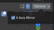
As our character is symmetrical in the x-axis, you could enable X-Axis Mirror 4.1.1 so that you can edit both sides at once. This only modifies the transformation of existing bones, however.
Therefore, it may be simpler to rig one side of the character and use the armature symmetrize command to mirror the rig. The benefit of this second method is that if you have set up bone constraints or modifiers, they will be mirrored across as well.
You must make sure to keep a good bone naming convention, both for ease of editing, and to make sure the symmetrize command works correctly. By appending “.L” to each bone that is specifically on the left hand side of the body, these will then be mirrored across to the right and renamed with a “.R” automatically by the symmetrize command. Bones in the middle like parts of the spine should be left without a suffix as they will not be mirrored.
I extruded out from the first bone to make the spine, then transformed and rotated them into position. I did the same with the left arm and left leg 4.2.1.


To position the bones in the middle of the limbs, I enabled Snap to Volume 4.2.2. This calculates the thickness of the object you are snapping to and positions the bone in the middle of the volume. By using this, it is easy to roughly position the bones into the mesh, before adjusting manually if needed.
Once the bones are in position, I can set up inverse kinematics to make the character easier to pose.
Whereas forward-kinematics is where you pose a character moving down towards the end of a chain of bones, inverse-kinematics works in the other direction. By giving a target for the end of the chain, it will automatically calculate how to reach that position by posing all the bones along the length of the chain. This is very useful for when a character must hold onto something, as you can animate the character body moving but the hands will continue to reach towards their targets.

I created an extra bone for the hand and foot target, and a pole target for each which controls the direction in which the elbow should bend. 4.3.1 As these bones are only targets for the rest of the armature, I disabled deform in the Bone Properties so that they would not deform the mesh.

In the Bone Constraints tab, I added an Inverse Kinematics bone constraint 4.3.2 to the hand and foot, set their chain length, and assigned their targets.
Now that the left half of the rig is completed, I used the symmetrize command to mirror it to the other side, completing the rig. This also mirrors all the constraints, which include the inverse kinematics.


Now the rig is complete 4.3.3 and can be moved in Pose Mode, which is separate to Object and Edit Mode. However, to make the mesh follow the bones, I parented the mesh to the armature with automatic weights. This calculates how much influence over the mesh each bone should be given. Now as I move the bones in Pose Mode, the mesh follows the armature.

The mesh is now parented to the armature, and vertices are influenced by each bone by a previously calculated amount. However, when posed into certain positions, there might be some strange stretching, or clipping in the mesh. 4.4.1
This is due to bones influencing vertices that they should not be influencing, but which might have been close to the bone in the resting pose when the weights were automatically calculated.
Humanoid characters are usually modelled in a T or an A pose 4.4.2 for this reason - with their arms away from their body - so that bones along the arm are less likely to get influence over the sides of the torso.


There is nothing to worry about if problems are present however, as it is possible to manually change the influence of each bone.
This is through a process called weight painting 4.4.3, and is in a separate mode to Object, Edit, and Pose mode. By selecting each bone in the vertex group list, you can paint on the weights of influence for the vertices of the mesh, correcting any problems.

After painting the weights, clipping now does not occur in this pose 4.4.4 However, this may cause problems in different poses, so it is best to check with different character poses to compromise on the solution with the least significant problems.
When in a very extreme position, with the bones far from their resting position, it is almost impossible to have the mesh completely natural looking. However, weight painting the mesh to fix as many problems as possible in this state means that you unlikely to encounter any problems because the character will rarely reach a position this extreme.